傍晚时分,你坐在屋檐下,看着天慢慢地黑下去,心里寂寞而凄凉,感到自己的生命被剥夺了。当时我是个年轻人,但我害怕这样生活下去,衰老下去。在我看来,这是比死亡更可怕的事。——–王小波
写在前面
CSDN上看到这样一个问题,回答后所以顺便整理一下
一般情况下,三层交换机不直接连终端,太浪费了,可以连一个交换机然后再连终端
傍晚时分,你坐在屋檐下,看着天慢慢地黑下去,心里寂寞而凄凉,感到自己的生命被剥夺了。当时我是个年轻人,但我害怕这样生活下去,衰老下去。在我看来,这是比死亡更可怕的事。——–王小波
案例
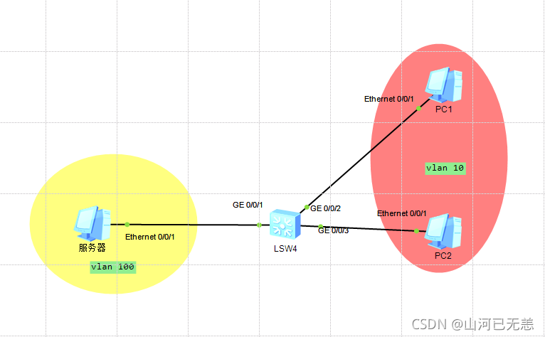
需求:实验室有一条接入网线,该网线直接连接PC,PC的IP设置为 192.168.100.xxx 后可以访问服务器机房的服务器(IP为192.168.100.1),但是想要实验室内的多台PC都能访问 192.168.100.1,请问交换机应该如何配置?
拓扑图 设计拓扑图
拓扑图。配置
配置三层交换机
配置终端IP
ping测试
配置 配置三层交换机 在三层交换机LSW上创建VLAN 1 2 3 4 5 6 7 8 9 10 11 12 13 14 15 16 17 18 19 Please press enter to start cmd line! <Huawei>syst <Huawei>system-view Enter system view, return user view with Ctrl+Z. [Huawei]vlan batch 100 10 Info: This operation may take a few seconds. Please wait for a moment...done. [Huawei] Oct 16 2021 14:06:41-08:00 Huawei DS/4/DATASYNC_CFGCHANGE:OID 1.3.6.1.4.1.2011.5 .25.191.3.1 configurations have been changed. The current change number is 4, th e change loop count is 0, and the maximum number of records is 4095. [Huawei]quit <Huawei>undo terminal debugging Info: Current terminal debugging is off. <Huawei>undo terminal monitor Info: Current terminal monitor is off. <Huawei>undo terminal logging Info: Current terminal logging is off. <Huawei>undo terminal trapping Info: Current terminal trapping is off.
将接口加入到对应VLAN中 1 2 3 4 5 6 7 8 9 10 11 12 13 14 15 <Huawei>system-view Enter system view, return user view with Ctrl+Z. [Huawei]interface GigabitEthernet 0/0/1 [Huawei-GigabitEthernet0/0/1]port link-type access [Huawei-GigabitEthernet0/0/1]port default vlan 100 [Huawei-GigabitEthernet0/0/1]quit [Huawei]port-group 2 [Huawei-port-group-2]group-member GigabitEthernet 0/0/2 GigabitEthernet 0/0/3 [Huawei-port-group-2]port link-type access [Huawei-GigabitEthernet0/0/2]port link-type access [Huawei-GigabitEthernet0/0/3]port link-type access [Huawei-port-group-2]port default vlan 10 [Huawei-GigabitEthernet0/0/2]port default vlan 10 [Huawei-GigabitEthernet0/0/3]port default vlan 10 [Huawei-port-group-2]quit
在三层交换机上给VLAN配置网关 1 2 3 4 5 6 7 8 9 10 11 12 13 14 15 [Huawei]interface Vlanif 100 [Huawei-Vlanif100]ip address 192.168.100.254 24 [Huawei-Vlanif100]quit [Huawei]interface Vlanif 10 [Huawei-Vlanif10]ip address 192.168.10.254 24 [Huawei-Vlanif10]quit [Huawei]display ip routing-table | include /24 Route Flags: R - relay, D - download to fib ------------------------------------------------------------------------------ Routing Tables: Public Destinations : 6 Routes : 6 Destination/Mask Proto Pre Cost Flags NextHop Interface 192.168.10.0/24 Direct 0 0 D 192.168.10.254 Vlanif10 192.168.100.0/24 Direct 0 0 D 192.168.100.254 Vlanif100 [Huawei]
配置终端
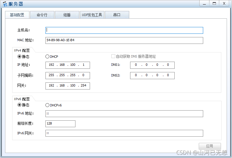
服务器 1 2 3 4 5 6 7 8 9 10 11 12 13 14 15 16 17 18 19 20 PC>ipconfig Link local IPv6 address...........: fe80::5689:98ff:fea0:1eb4 IPv6 address......................: :: / 128 IPv6 gateway......................: :: IPv4 address......................: 192.168.100.1 Subnet mask.......................: 255.255.255.0 Gateway...........................: 192.168.100.254 Physical address..................: 54-89-98-A0-1E-B4 DNS server........................: PC>ping 192.168.10.2 Ping 192.168.10.2: 32 data bytes, Press Ctrl_C to break From 192.168.10.2: bytes=32 seq=1 ttl=127 time=110 ms From 192.168.10.2: bytes=32 seq=2 ttl=127 time=47 ms From 192.168.10.2: bytes=32 seq=3 ttl=127 time=46 ms --- 192.168.10.2 ping statistics --- 3 packet(s) transmitted 3 packet(s) received 0.00% packet loss round-trip min/avg/max = 46/67/110 ms
PC1 1 2 3 4 5 6 7 8 9 10 11 12 13 14 15 16 17 18 19 20 Welcome to use PC Simulator! PC>ipconfig Link local IPv6 address...........: fe80::5689:98ff:fea7:1ca1 IPv6 address......................: :: / 128 IPv6 gateway......................: :: IPv4 address......................: 192.168.10.2 Subnet mask.......................: 255.255.255.0 Gateway...........................: 192.168.10.254 Physical address..................: 54-89-98-A7-1C-A1 DNS server........................: PC>ping 192.168.100.1 Ping 192.168.100.1: 32 data bytes, Press Ctrl_C to break From 192.168.100.1: bytes=32 seq=1 ttl=127 time=47 ms From 192.168.100.1: bytes=32 seq=2 ttl=127 time=31 ms --- 192.168.100.1 ping statistics --- 2 packet(s) transmitted 2 packet(s) received 0.00% packet loss round-trip min/avg/max = 31/39/47 ms
PC2 1 2 3 4 5 6 7 8 9 10 11 12 13 14 15 16 17 18 19 20 PC>ipconfig Link local IPv6 address...........: fe80::5689:98ff:fe84:2ce2 IPv6 address......................: :: / 128 IPv6 gateway......................: :: IPv4 address......................: 192.168.10.3 Subnet mask.......................: 255.255.255.0 Gateway...........................: 192.168.10.254 Physical address..................: 54-89-98-84-2C-E2 DNS server........................: PC>ping 192.168.100.1 Ping 192.168.100.1: 32 data bytes, Press Ctrl_C to break Request timeout! From 192.168.100.1: bytes=32 seq=2 ttl=127 time=47 ms From 192.168.100.1: bytes=32 seq=3 ttl=127 time=47 ms From 192.168.100.1: bytes=32 seq=4 ttl=127 time=47 ms --- 192.168.100.1 ping statistics --- 4 packet(s) transmitted 3 packet(s) received 25.00% packet loss round-trip min/avg/max = 0/47/47 ms
一般的解决方案 综合组网 案例(更合理的使用三层交换机):交换机、三层交换、路由构建网络
需求:实验室有一条接入网线,该网线直接连接PC,PC的IP设置为 192.168.4.xxx 后可以访问服务器机房的服务器(IP为192.168.5.1),但是想要实验室内的多台PC都能访问 192.168.5.1,请问交换机应该如何配置?
综合组网
第一步:设计好网络拓扑结构;为了缓解三层交换机的压力,通常连接外部网路需要连接一个路由器。路由器的功能要比三成交换机强大。
第二步:在PC1、PC2 和 PC3 及PC4 中配置IP地址,子网掩码和网关;1 2 3 4 PC1: IP地址:192.168.1.1/24 网关:192.168.1.254 PC2: IP地址:192.168.2.1/24 网关:192.168.2.254 PC3: IP地址:192.168.3.1/24 网关:192.168.3.254 PC4: IP地址:192.168.5.1/24 网关:192.168.5.254
第三步:在二层交换机 (S3700) LSW1上创建VLAN;1 2 <LSW1>system-view [LSW1]vlan batch 2 to 3
第四步:将接口加入到交换机 (S3700) LSW1相应的vlan中;
1 2 3 4 5 6 7 8 9 [LSW1]interface Ethernet 0/0/2 [LSW1-Ethernet0/0/2]port link-type access [LSW1-Ethernet0/0/2]port default vlan 2 [LSW1-Ethernet0/0/2]display vlan [LSW1]interface Ethernet 0/0/3 [LSW1-Ethernet0/0/3]port link-type access [LSW1-Ethernet0/0/3]port default vlan 3 [LSW1-Ethernet0/0/3]display vlan
第五步:在二层交换机LSW1 (S3700) 和三层交换机LSW2(S5700) 上配置trunk(中继链路)
1 2 3 4 5 6 7 8 9 10 11 12 13 [LSW1]interface Ethernet 0/0/4 [LSW1-Ethernet0/0/4]port link-type trunk [LSW1-Ethernet0/0/4]port trunk allow-pass vlan all [LSW1-Ethernet0/0/4]quit [LSW1]display current-configuration [LSW2]interface GigabitEthernet 0/0/1 [LSW2-GigabitEthernet0/0/1]port link-type trunk [LSW2-GigabitEthernet0/0/1]port trunk allow-pass vlan all [LSW2-GigabitEthernet0/0/1]quit [LSW2]display current-configuration
第六步:在三层交换机LSW2(S5700)上创建vlan,并将接口GE 0/0/2加入到vlan 4中
1
2
3
4
5
6
<LSW2>system-view [LSW2]vlan batch 2 to 4 [LSW2]interface GigabitEthernet 0/0/2 [LSW2-GigabitEthernet0/0/2]port link-type access [LSW2-GigabitEthernet0/0/2]port default vlan 4 [LSW2-GigabitEthernet0/0/2]display vlan
1
2
3
4
5
6
7
<AR1>system-view [AR1]interface GigabitEthernet 0/0/0 [AR1-GigabitEthernet0/0/0]ip address 192.168.4.2 24 [AR1]interface GigabitEthernet 0/0/1 [AR1-GigabitEthernet0/0/1]ip address 192.168.5.254 24 [AR1]display ip routing-table | include /24
第九步:在三层交换机LSW2(S5700)上配置静态路由
1
2
3
<LSW2>system-view [LSW2]ip route-static 192.168.5.0 24 192.168.4.2 [LSW2]display ip routing-table | include /24
第十步:在路由器AR1(AR2220) 上配置静态路由
1
2
3
4
5
<AR1>system-view [AR1]ip route-static 192.168.1.0 24 192.168.4.1 [AR1]ip route-static 192.168.2.0 24 192.168.4.1 [AR1]ip route-static 192.168.3.0 24 192.168.4.1 [AR1]display ip routing-table | include /24
![[外链图片转存失败,源站可能有防盗链机制,建议将图片保存下来直接上传(img-miywkSVO-1616539978055)(imgclip_4.png "imgclip_4.png")]](https://img-blog.csdnimg.cn/20210324065528408.png?x-oss-process=image/watermark,type_ZmFuZ3poZW5naGVpdGk,shadow_10,text_aHR0cHM6Ly9ibG9nLmNzZG4ubmV0L3Nhbmhld3V5YW5n,size_16,color_FFFFFF,t_70)